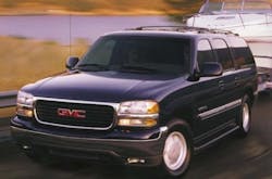
AutoFocus: Turn, turn, turn -- understanding GM’s Quadrasteer system
Do you remember taking your test for your driver’s license? I’ll bet you chose a car and left your truck at home. Good choice. Trucks do a lot of things well, but maneuvering easily has not always been one of them. In 2003, however, General Motors added 4-wheel steering as an option on several of its trucks.
This “Quadrasteer” system dramatically reduces turning radius and improves overall handling. Here is what you need to know about it.
When vehicles with Quadrasteer back in and out of a parking place, they are assisted by the rear wheels, as is changing direction during forward motion. The system can be set in a “towing” mode which allows the rear wheels to add more stability while pulling a trailer. Before we get into the specifics of how it works, let’s discuss some of the operating characteristics.
Quadrasteer has three driving phases: negative, neutral and positive.
The Negative phase is used for low speed maneuvers up to 45 mph. This is where the rear wheels turn opposite to the front wheels. This phase is limited to a maximum of 12 degrees rotation at slow speeds and gradually decreases to zero degrees at 45 mph.
The Neutral phase is used when the driver selects front-wheel steering only, or at 45 mph in the 4-wheel steering mode.
The Positive phase begins after 45 mph and is used when the rear wheels turn in the same direction as the front wheels. This is limited to a maximum arc of 5 degrees and decreases with speed. When the transmission is in “Park,” rear wheel steering is limited to five degrees to avoid excessive tire wear.
Four central components are used in this system: the Mode Selector Switch, the Rear Wheel Steering Control Module, the Handwheel Position Sensor and the Steerable Rear Axle.
1. The Mode Selector Switch has three positions: 2WS, 4WS and Tow. The Tow mode operates the same as the 4WS mode, except that the crossover from the negative to the positive steering phase occurs at 25 mph instead of 45 mph. The current mode selection is identified by the illumination of mode lamps on the selector switch. When a different mode is selected, the indicator lamp for that mode will flash until the steering wheel is passed through “center” at which time the lamp will remain on steady. Having all lamps illuminated is an indication that the system needs an electrical alignment. If the transmission is placed in neutral, the system will default to the 2-wheel steering mode, making the rear wheels straight during a trip through the car wash.
2. The Rear Wheel Steering Control Module is located above the spare tire under the truck body. It receives several inputs from the powertrain control module (PCM) including speed information; steering wheel position from the handwheel position sensor; rear axle position from the rear position sensor; and vehicle directional movement from the yaw rate and lateral accelerometer sensor. The main outputs include control of the Steerable Rear Axle, feedback to the mode selector switch, and communication with the PCM via Class 2 data. Two codes are related to the system: CO550, which concerns a module failure and U1305, a Class 2 communication failure.
3. The Handwheel Position Sensor is located at the base of the steering column and gives the control module exact information about steering wheel position and the speed of position change. To reduce the chances of an inaccurate output, the sensor creates four different signals: one analog, three digital.
4. The Steerable Rear Axle is controlled by a rack and pinion, and is driven by a three-phase electric steering gear motor through a set of planetary gears at a ratio of 45 to 1. These gears are packed in synthetic grease for long life. If the system fails, two powerful return springs built into the rack force the rear steering back to a neutral position.
A rear wheel position sensor is built into the lower segment of the steering gear motor and provides constant output to the control module as to rear axle wheel position. This sensor provides two separate outputs for reliable readings and is replaceable as a separate unit.
Driving force is transmitted through quarter shafts connected to CV joints. The CV joint boots are not serviceable and require replacement of the entire shaft. Steering motion is done through upper and lower ball joints and tie rod ends. These joints are sealed and do not have lubrication fittings. The rear axle has both a drain and a fill plug and both are accessible without removal of any Quadrasteer component. Synthetic lubricant is used with a capacity of approximately three liters.
Although Quadrasteer is an expensive option, it’s well worth the investment for those who need to maneuver in tight spaces. You may even see a few trucks at the driver testing station!
