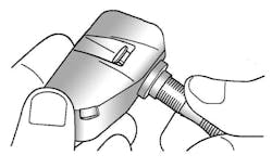
Low- and high-line versions of TPMS receivers on the Hyundai Elantra
SUBJECT VEHICLE: 2008-10 Hyundai Elantra.
SENSOR IN TIRE? No, sensors are mounted in the wheels.
SPECIAL TOOLS NEEDED? Yes, a TPMS exciter scan tool.
The tire pressure monitoring system (TPMS) on 2008-10 Hyundai Elantras uses a receiver that is available in low-line and high-line versions. There are four radio frequency (RF) tire pressure sensors, two warning indicators on the instrument cluster and a data circuit to perform system functions. Vehicles with high line systems have three warning indicators and include four low-frequency initiators (LFIs). When tire pressure is below the allowed threshold, or a rapid leak is detected, the low pressure warning light on the instrument cluster will be illuminated. On vehicles with a high line system, a tire location light also will illuminate to indicate the faulty tire.
If the system detects a receiver or sensor fault, or if it detects a fault that is external to the receiver or sensor, the TPMS warning indicator on the instrument cluster will be illuminated. If the fault is considered “critical,” the light will stay on throughout the entire ignition cycle.
In order to remove an old sensor and install a new one, follow these steps:
1. Remove the wheel and tire assembly. CAUTION: Avoid tire/tool contact with the valve while demounting the tire.
2. Deflate the tire and remove the balance weights. The bead should be broken about 180 degrees from the valve side of the wheel. The bead breaker should not be set too deep. Demount should end near the valve. CAUTION: The valve nut should not be re-used.
3. While handling the sensor with care, remove the valve nut.
4. Discard the valve immediately.
5. Assemble the valve to the sensor, and turn the valve three times with the square part of the screw in the slot. See Figure 1. CAUTION: Ensure the sensor feet are against the wheel throughout the remainder of the assembly process.
6. Ensure that the valve hole and mating face of the wheel are clean. Mount the assembly to the wheel. The fit should not be tight (it should still be possible to easily adjust the valve angle). CAUTION: Ensure the grommet remains in contact with the wheel.
7. Tighten the washer and nut by hand until the valve thread meets the nut’s built-in calibrated stop.
8. Using an appropriate torque wrench, tighten the nut to 31 to 40 in.-lbs. (3.5-4.5 N.m). It is normal to feel a break as the 20 in.-lbs. (2.3 N.m) calibrated stop in the nut snaps and the torque falls. Increase the torque smoothly in order to achieve a clean break of the stop.
9. Lubricate the tire bead (not the rim). Do not use excessive lubrication.
10. Start mounting the tire about 5.9 inches from the valve. Move the mounting tool away from the valve. Avoid tire/tool contact with the valve. Finish with the mounting tool near the valve.
11. Adjust inflation pressure of wheels. Install the valve cap.
12. If installing a new sensor, it must be initiated.
To initiate the tire pressure sensor, follow these steps:
1. Holding the TPMS exciter scan tool within three inches of the sensor valve, read each tire pressure sensor ID in the following order: front-left, front-right, rear-left, rear-right.
2. Connect the TPMS exciter to the Data Link Connector located under the left side of the instrument panel. Register the four sensor IDs to the receiver. See Figures 2 and 3.
3. Disconnect the TPMS exciter from the diagnostic link. Cycle the ignition and wait four minutes. Ensure that “NORMAL RECEIVER STATE” is displayed.
Information for this column comes from Mitchell 1’s ”Tire Pressure Monitoring Systems Guide” for domestic and import vehicles through 2010. Headquartered in Poway, Calif., Mitchell 1 has provided quality repair information solutions to the automotive industry for more than 80 years. For more information, visit www.mitchell1.com.


