Wheel alignment theory: Optimum handling requires properly adjusting the angles
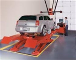
Granted, a state-of-the-art computerized wheel alignment system will walk a technician through the steps and will perform all necessary calculations. It also will instruct the technician to adjust angles in order to meet original equipment specifications for a specific production vehicle.
However, instead of blindly following the dictates of a machine, it's important for your technicians to understand wheel angles and what these angles represent in terms of drivability, braking, tire wear and handling. In other words, they need to understand wheel alignment theory.
Only by grasping the rudiments of wheel angles will they be able to appreciate how they affect the vehicle in motion. A number of dimensional angles are involved in wheel alignment theory, but only three of these angles are generally considered adjustable. They are wheel toe, camber and caster. Here's an explanation of each of these adjustable angles from me directly to your techs, followed by an overview of all wheel angle factors involved in achieving optimum handling, braking and tire life.
TOE ANGLE
The relationship of the right and left wheels on the same axle, as viewed from overhead, illustrates the toe angle. Toe angle is achieved by comparing the distance between the center of the front of the tires to a distance between the centers of the rear of the tires on the same axle.
* "Toe-in" is present when the two wheels on the same axle are closer together at the front and wider apart at the rear. A toe-in condition is also called positive toe angle.
* "Toe-out" is present when the wheels are further apart at the front and closer together behind the axle centerline. A toe-out condition is also called negative toe angle).
* "Zero toe" is present when the distance between the front of the wheels (ahead of axle centerline) is identical to the distance between the wheels behind the axle centerline.
[PAGEBREAK]
All front suspensions, regardless of design, feature toe angle adjustment at a location on the steering tie rods/tie rod ends. Live rear axles will feature no toe angle adjustment, since this is a fixed angle. Independent rear suspensions usually offer rear wheel toe adjustment.
The toe angle affects directional control, turning response and tire tread life. Toe-related tread wear will cause a "feathering" wear pattern across the tread. If too much toe-in is present, the feathering will angle toward the center of the vehicle. If too much toe-out is present, the feathering will angle toward the outside of the vehicle.
Due to compliance in control arm bushings and other dynamic variances in the suspension and steering system, we want to establish a static (vehicle sitting stationary on level surface) toe angle that will result in zero-toe when the vehicle is driven down the road in a straight line. For this reason, the initial, or static, toe setting may be slightly positive or slightly negative.
Commonly, a rear-drive vehicle would likely require a front wheel toe-in (positive) setting, and a front-wheel-drive vehicle would likely require a slight toe-out (negative) setting. As a rear-drive vehicle moves forward, the front wheels tend to try to push outboard, like they are trying to crawl away from each other, while a front-wheel-drive vehicle's front wheels try to crawl inboard as the vehicle accelerates forward.
Bear in mind that if stiffer suspension bushings are installed (specifically control arm bushings), toe may not change as much from static to dynamic conditions, so it may very well be possible to set front toe angle closer to zero in a static state.
Never guess about any alignment angle. Always refer to the OE specifications, unless you're tuning a competition car for the demands of a particular course.
[PAGEBREAK]
CAMBER ANGLE
A wheel's camber angle refers to the "lean" of the wheel from top to bottom when viewed from the front or rear of the vehicle. A wheel/tire that leans out at the top (as compared to a true vertical) features positive camber. If the wheel/tire is straight up (following a true vertical), this is called zero camber. A wheel/tire that leans inboard at the top (as compared to a true vertical reference line), exhibits negative camber.
If the wheel/tire features a static negative camber angle (i.e., when the vehicle is sitting idle), more tread load is placed at the road surface on the inner shoulder/tread area. Negative camber is regularly employed on performance vehicles (especially race cars on road courses) in order to increase the tire contact patch during hard turns. Since lateral loading (when the car goes into a hard turn) will try to push the top of the inside tire outward, adequate negative camber may be dialed in to compensate for this.
So, while the front wheels may display negative camber as it rolls straight, when it goes into a hard turn, the wheel facing the direction of the turn will try to "straighten up," achieving maximum tread contact with the road. If the camber angle isn't sufficiently negative, this tire will lean too far, causing the inside of the tread to lift and placing excess stress and load only on the outside of the tread and outer shoulder.
This does not mean that street vehicles should have tons of negative camber, since normal street driving will result in excess wear on the inside tire shoulder and tread area. Camber angle always must be adjusted to maximize the tread contact patch based on the driving requirements. In most cases, OE specifications will call for a slightly positive or zero camber angle in order to maximize tire wear and traction, and to provide easier steering and greater resistance to directional "darting" in a straight line.
Unless you're tuning a suspension for a specific race track that demands a unique individual wheel camber setting, generally the camber angle will be close to identical side-to-side. If camber angles differ appreciably, the car will pull in straight lines and under braking, always pulling toward the side with less negative camber. For instance, if the left front wheel has three degrees negative camber but the right front wheel has one degree negative camber, the car will pull to the right.
[PAGEBREAK]
Front suspension camber angles are adjustable, but the level of difficulty varies depending on suspension design. If an upper/lower control arm is involved, the upper or lower arm can be adjusted by either adding or removing adjuster shims between the upper arm and frame, or by rotating an eccentric shaft or washers. In some cases, the lower arm may be adjustable via eccentric shaft/washers. If more negative camber is required, the upper arm can be moved further inboard, or the lower arm can be moved further outboard. Conversely, if more positive camber angle is needed, the upper arm can be moved outboard, or the lower arm can be moved inboard.
On strut-equipped vehicles, camber may be adjustable in one of two ways: by adjusting the top of the strut mount inboard/outboard at the upper towers, or by adjusting an eccentric at the lower mount, where the strut attaches to the steering knuckle upright. If the OE setup does not allow adjustment, aftermarket adjusters are readily available for either top-strut or bottom-strut applications.
Rear camber may or may not be adjustable, depending on the type of rear suspension. If a live axle is present (a rigid, one-piece axle housing on a rear-drive vehicle), camber likely won't be adjustable. However, if an independent rear axle is featured, camber should be adjustable either via eccentric bushings at the inboard control arm pivot points, or by means of an eccentric at the strut-to-rear upright.
If adjustment is available (either through OE design or with the use of aftermarket adjusters), it's best to adhere to OE specifications for street driving. The only need to vary this is if the vehicle is being set up for competition use, in which case the same rules apply that are required up front -- to obtain the maximum tread contact patch based on track requirements.
Camber angle directly affects tire wear, since the camber angle may contribute to excessive inner or outer tread wear if not adjusted properly.
[PAGEBREAK]
CASTER ANGLE
Caster angle involves only the front, or steering end, of the chassis. The caster angle, or steering axis angle, involves the relationship of the upper ball joint (or top of the strut mount) to the lower ball joint as viewed from the side of the vehicle.
Using a true vertical drawn through the hub center as a reference, caster angle is represented by a straight line drawn through the upper ball joint/pivot location through the lower ball joint. All vehicles should feature a "positive" caster angle, where the upper suspension pivot point is located behind the lower pivot point (again, as compared to a true vertical).
If the caster angle is zero (where the lower pivot is directly below the upper pivot), directional control will suffer, and there would be little, if any, steering wheel return.
If the caster angle is negative (where the upper pivot point is located ahead of the lower pivot), the vehicle will be virtually undriveable due to extremely poor directional control.
Like camber, the caster angle is measured in degrees. The caster angle is a major contributor to directional control. A too-small (not positive enough) caster angle may make the vehicle too twitchy (but would require less driver input to turn the wheel), especially as speed increases.
Theoretically, the greater the caster angle, the more directional control you'll have at higher speeds (which also requires slightly more driver input at the steering wheel). However, all suspension systems are designed to perform best at a specific caster angle, so always follow the OE specification in order to achieve the correct balance between turning effort and vehicle stability control.
Front caster angle may or may not be readily adjustable, depending on suspension design. If the front suspension features upper and lower control arms, the upper arm likely will be adjustable, either via the addition or removal of shims between the upper arm and frame or via eccentric bushings. If an upper/lower control arm system is featured, the two anchoring locations (where the upper arm attaches to the frame) can be adjusted, again, with shims or eccentrics.
To alter camber, the adjustment must be performed equally at front and rear attachment points in order to move the upper arm pivot inboard or outboard. If the vehicle features MacPherson-type struts, the top of the strut can be moved forward or rearward to alter the caster angle since the top strut mount serves as the upper locating point.
On most strut-equipped vehicle, no OE caster adjustment is readily offered. However, aftermarket adjustable strut mounts are available which allow you to move the top of the strut fore/aft and inboard/outboard for caster or camber.
While the caster angle itself is not a direct tire-wear angle, improper caster angle can contribute to excessive tire wear in conjunction with improper camber and toe angles.
[PAGEBREAK]
TURNING RADIUS AND TOE-OUT ON TURNS
Because of the travel arc that occurs when the wheels are turned (due in part to the caster angle and steering axis inclination), individual wheel toe angles will change compared to their straight-ahead static settings.
For example, when the steering wheel is turned to the left, the left front wheel will exhibit greater toe-out as compared to the number of degrees that the right front wheel toes-in. This phenomenon, designed into the suspension system, decreases the turning radius of the vehicle and helps to prevent tire scrubbing during turns.
STEERING AXIS INCLINATION
Steering axis inclination, also called SAI, represents a predetermined and non-adjustable angle between a true vertical drawn through the center of the tire and a line drawn through the upper and lower ball joints when viewed from the front of the vehicle. The angle resulting from where these two lines intersect represents SAI. In a way, you can view SAI as the built-in-by-design "camber" of the suspension system.
Included angle (IA) is the combination of SAI and wheel camber. Both SAI and IA are measured to verify that the fixed angles (those angles that exist by design) are correct.
If SAI or IA is outside of the OE specification, it's apparent that a chassis location has been damaged (a strut is bent, the strut tower has deformed, a lower control arm is bent, etc.).
SCRUB RADIUS
Scrub radius represents the "pivot point" created by the force of the load and the steering axis. As viewed from the front of the vehicle, this is determined by considering the distance between the center of a front tire tread and the imaginary SAI line, when measured at the road surface.
Since these two lines eventually will intersect, it's this intersection point that we're really interested in.
* When the two lines crisscross exactly at the road surface, the resulting condition is zero scrub.
* When the lines crisscross above the road surface, the resulting condition is negative scrub.
* When the lines intersect below the road surface, the resulting condition is positive scrub.
An excessively negative scrub radius will require greater steering effort, while excessive positive scrub radius (where the tread center essentially moves further outboard) can not only affect handling and ease of steering, but also over-stress wheel bearings.
In most cases, a short arm/long arm suspension (upper and lower control arms where the lower arm is longer) will exhibit a positive scrub radius.
A MacPherson strut front suspension commonly features a negative scrub radius, which aids in minimizing "torque steer," a common trait on front-wheel-drive vehicles. With torque steer, the front wheels tend to pull in one direction under hard acceleration, especially from a standing take-off.
[PAGEBREAK]
GEOMETRIC CENTERLINE
This is a line drawn from the center of the rear axle to the center of the front axle, as viewed from above the vehicle.
THRUST LINE AND THRUST ANGLE
The thrust line represents the forward direction of the rear axle wheels as viewed from above. It is the direction that the rear axle aims. Not to be confused with the geometric centerline, the thrust line effectively divides left and right rear wheel toe. The thrust line may or may not follow the geometric centerline.
The thrust angle exists as the difference between the geometric centerline and the thrust line, measured in degrees. If the thrust angle bears to the right, it is a positive thrust angle. If it bears to the left, it's a negative thrust angle.
CENTERLINE STEERING
Centerline steering is simply a term that refers to a "straight and level" steering wheel clock position when the vehicle rolls in a straight line. If the steering wheel is not centered, this may indicate a possible thrust angle deviation.
TYPES OF WHEEL ALIGNMENT
The old two-wheel, geometric centerline approach is an outdated alignment procedure, in my opinion, because it does not take into consideration the rear wheel positions. As such, it simply isn't effective, because it ignores the thrust direction of the rear axle.
A much more effective method is "thrust line" or "thrust angle" alignment, which considers the actual location and direction of the rear wheels. This allows you to adjust the front wheel angles relative to the rear wheel angles, regardless of geometric centerline.
If the vehicle in question features rear wheel toe adjustment, we can achieve optimum wheel alignment using the total four-wheel approach, by referring to and adjusting the vehicle thrust angle to as close to zero as possible.
If the thrust angle is "off zero," this can contribute to vehicle dog-tracking (crooked body relative to direction of travel), increased tire wear and unequal left/right turning. Total four-wheel alignment allows you to adjust and hopefully correct rear axle thrust angle, which allows you to adjust the front wheels parallel to the rear wheels.
If the vehicle does not allow rear wheel angle adjustment, take advantage of a four-wheel thrust line alignment approach. If the vehicle allows adjustment of the rear wheel angles, perform a "total" four-wheel alignment.
[PAGEBREAK]
DON'T IGNORE THE OBVIOUS!
The best wheel alignment equipment coupled with the best of intentions can all be for naught if you don't first inspect vehicle ride height; the condition of the wheel bearings, ball joints and tie rods; and tire inflation.
Worn and sloppy pivot joints will allow wheel angles to change from their adjusted static positions on the alignment rack, once the vehicle is driven off the rack and onto the road. If suspension height is uneven due to worn or damaged springs, you won't be able to achieve wheel alignment that will function properly. If the suspension height has been altered intentionally (lowered or raised), only use the OE specs as a guideline, since you may not be able to meet them fully.
Toe adjustment is easy and should always offer enough range to meet OE specs. Try to keep caster and camber as close as possible to spec, which may require the use of aftermarket adjustment aids.
Finally, always verify tire inflation pressure before attempting a wheel alignment, since changes in inflation result in changes in the distance between the axle centerline and the ground, which will affect wheel angles.
ALTERING SUSPENSION HEIGHT: requires re-aligning the wheels
It's important to note that whenever a vehicle is either lowered or raised, the wheels must be re-aligned. A byproduct of altering suspension height is an immediate change of camber, caster and toe angles.
If the suspension is raised, camber likely will move toward the positive side, caster will move toward the negative side, and toe will either move in or out, depending on the location of the steering arms (the steering arm may be located forward of the hub center or rear of the hub center, depending on where the auto maker mounted the steering rack or steering box arm).
If the vehicle is lowered, camber will move negative, caster will move positive, and toe will change as noted earlier.


