Do you know the most common cause of vehicle vibration complaints in modern automobiles?
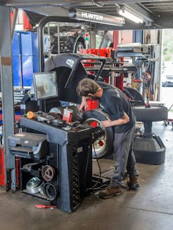
Greg Meyer at Hunter Engineering Co. says it’s wheels and tires. And that means the proper balancing of wheel and tire assemblies has never been more important.
“Even drivers of pickup trucks demand a smooth ride today,” says Meyer, a senior product manager for Hunter.
The training team at Snap-on Inc. says the combination of low-profile sidewalls, high-traction tread compounds and aggressive tread patterns all can make balancing high performance (HP) and ultra-high performance (UHP) tire assemblies even trickier.
Lots of factors contribute to getting it just right. But Snap-on believes spending an extra 20 or 30 seconds is worthwhile to prevent comebacks and ensure customer satisfaction.
Professional technicians are well-served by following proper techniques and using well-maintained equipment. And as Meyer notes, independent tire dealers reap the rewards when consumers receive top-notch service.
“Providing a smooth ride to every customer makes you more likely to succeed in today’s market,” he says.
With so much riding on those smooth rides, we asked the manufacturers of balancing equipment to break down common problems and misconceptions as it pertains to balancing HP/UHP tires and wheels.
Experts from three equipment makers responded with 22 tips to help tire technicians get the job right the first time.
Kyle Harris, product manager, Coats Co.:
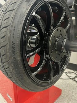
Wheel not properly centered: Balancing today’s high-performance wheels require the utmost attention to detail when it comes to mounting on the balancer. A UHP tire and wheel combo that is not centered on the balancer will not balance properly. The best way to balance any wheel on a balancer is to use a double-sided collet from the back side of the wheel. For many years, electronic wheel balancing was performed on steel wheels simply using a cone from the front side of the wheel. Wheels are designed to center on the vehicle from the back side. This is why when balancing using a collet from the back side is the best way to accurately center a wheel. Also using a collet rather than a traditional cone means no chance of cracking expensive plastic cladding on OEM wheels. For today’s UHP tire and wheel combinations, centering from the back side of the wheel with a collet is the best way to ensure a well a balanced assembly.
Incorrect mounting: The days of using a cup and rubber ring on the outside of a wheel when balancing are long behind us, as an industry. Today’s heavy and large diameter assemblies require that the wheel be uniformly set against the collet for proper centering. Using a cup with a rubber ring can cause the wheel to ‘climb’ the collet improperly when the wing nut is tightened, leading to a non-centered condition. In addition to this, rubber rings can scratch and mar the finish on sensitive, high performance wheels. Using a pin plate or a flange plate is the best way to ensure that the wheel climbs the collet evenly when the wing nut is tightened. It also protects the wheel from damage caused by dirt and debris that may be embedded into the rubber ring.
Wheel is heavy and difficult to mount on balancer: High performance wheels and tires often come in large diameters and very high negative offsets. This can make keeping the wheel and the centering tooling lined up on the balancer shaft a challenge while tightening down the balancer wing nut. Using a proper wheel lift for these wheels can not only prevent back and finger injuries to the technician, but can also help eliminate accidental damage to the wheel from any other tooling coming in contact with a black powder coated or polished finish wheel. Having a wheel lift present makes using the proper balancer tooling quick and easy for a technician even when the wheel’s weight exceeds 100 pounds.
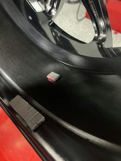
Balancer is not in the correct mode: When a technician is working at a busy shop and is faced with balancing a set of UHP tires and wheels, sometimes paying attention to the small details can make a huge difference. An inspection of the wheel can tell a technician a lot about how a wheel should be balanced. For example, does this UHP tire and wheel combination have provisions for clip weights on the inner plane? If so, the technician should take note and place the balancer in clip/tape mode and measure the wheel appropriately. Does the wheel have spokes that the technician can hide the weights behind on the outer plane? If so, place the balancer in ‘behind spoke mode’ and place wheel weights strategically behind spokes. Also, if the wheel is black, have an assortment of black adhesive weights in the correct denominations to make these wheels look great when they are balanced.
Aftermarket wheels vibrate and hub-centric rings are missing: Aftermarket wheels can often be used on multiple vehicles requiring the use of hub centric adapter rings to adapt the wheels to different vehicle hub bore sizes. It is very common for these rings to fall out or become damaged during the process of mounting new tires and balancing a set of wheels. Many times, a technician will find these left on the balancer shaft or on the floor after the vehicle has already left. If the rings are missing or damaged, the wheel cannot center properly on the car and this will cause a vibration at speed. The best way to prevent this is to identify the presence of the hub centric rings on a wheel before it is balanced and carefully remove them for balancing. Once balancing is complete, the rings can be reinstalled. If the rings are missing or become damaged, simply replace the rings with a set made of a solid material, such as aluminum or polymer, that fits tightly against the hub of the vehicle and fits snugly inside the hub bore center of the wheel. If the wheel cannot be centered on the vehicle, it doesn’t matter how well balanced it is.
Greg Meyer, senior product manager, Hunter Engineering Co.:
Vibration: Vehicles with UHP wheels and tires are generally more sensitive to vibrations due to suspension designs. Customers who drive these vehicles are often more particular about their vehicles. It all starts with proper mounting techniques, proper lubrication and bead exercising (massage) to ensure the tire is on the rim properly. A diagnostic balancer is essential for finding and fixing these issues before the customer does. You can’t find/fix what you don’t measure. Modern balancers can measure these vibrations without a time penalty.
Most problem assemblies can be fixed by just rotating the tire on the rim as prescribed by a diagnostic balancer. Centering problems are recognized by the industry as the number-one problem in balancing. If a wheel isn’t centered on the balancer, all of the points mentioned above are nullified. Verify proper centering with every new assembly. This can be done by spinning an assembly in static mode and noting the amount and location of the weight callouts. Without installing these weights, loosen and turn the assembly on the balancer shaft and spin again. The second callout should be within 30 degrees and 0.5 ounces of correction weight callout. If not, check your mounting setup and try again. You can also invest in a balancer that verifies centering for you automatically, so you don’t have to perform this procedure. Balancers are electronic machines that require calibration. Make sure you are calibrating your machine daily or invest in a machine that performs this calibration automatically.
‘Bad’ tires causing vibrations: There are ‘bad tire’ out there that are manufactured incorrectly, but with proper tire mounting techniques and ForceMatching with a diagnostic balancer, only a few percent of tires will need to be returned. The vast majority of tires returned to tire manufacturers have no issues.
‘Bad’ balancing causing vibrations: Yes, there are balancing mistakes that are made. Centering and improper calibration are two that are common and should always be verified. Centering and calibration can be perfect and still have vibration issues due to bent rims, tire construction or tire mounting issues.
Few comebacks: Comebacks are like the tip of the iceberg. Many (customers) who are unsatisfied never come back and will likely not recommend your shop to others. The bulk of the problem lies beneath the surface of the water!
No time: On average, less than a third of assemblies need to be addressed with ForceMatching (turning the tire on the rim). This procedure takes just a couple of minutes with a tire changer with bead rollers. Customer comebacks take more than an hour to address, which is much more costly. Lost business is even more expensive.
Swap and drive: This technique may work when there is a single assembly with an issue, but it becomes almost impossible when dealing with two problem assemblies. Often all four tires end up being considered ‘bad’ and are replaced. This is an expensive proposition. In any case, this sort of diagnostic strategy is always time-consuming, (and involves) lifting and driving the car multiple times and is generally considered a last resort.
Bead seating problem: Some believe tire issues are caused when the beads don’t seat properly. Studies have shown that in the majority of cases where assemblies have high radial force variation (road force) not caused by tire construction, the beads are seated in the bead seat area of the rim. The cause of the radial force variation is often due to bead stress. Think of the beads as being twisted as they slide into place, but they are in their proper location. The beads being twisted causes the tire to have inconsistent stiffness around the sidewall and causes variation as the tire rolls. Performing a bead massage can often reduce this stress and lower road force.
New tires don’t require a road test: If you aren’t checking the quality of your work, your customers are doing this for you. If they find a problem, they are faced with the decision to bring the vehicle back or just deal with the problem. The latter probably means they won’t recommend your shop to their friends. A road test ensures the vehicle is performing up to the expectations of modern customers. Alternately, using a diagnostic balancer that measures road force is as good or better than taking the vehicle for a road test. You are road testing each assembly on the balancer. If this test is good, the vehicle will ride smoothly.
Swapping is fixing: Swapping out a poorly constructed tire with a well-constructed tire can certainly fix an issue. But there are many cases where this won’t work. Putting a second good tire on a bent rim will almost certainly not fix a problem. You may be throwing away perfectly good tires, which are being improperly diagnosed due to poor mounting procedures.
Move tires to the rear: Many times, assemblies have significant issues and moving tires just moves the complaint. There are vehicles, such as pickup trucks, where placing the bad assembly on the back can make the problem worse. The best answer is to ensure all assemblies’ road force is within specs. This guarantees a happy customer.
The eye tests: You can see if a tire is mounted on the balancer correctly by watching it spin — sometimes. Gross centering errors can be seen by watching the assembly spin on the balancer. Only 0.010-of-an-inch of centering error will cause just over one ounce of imbalance error and is almost impossible to see with the human eye, but is more than enough to cause a vibration on some vehicles. A better method is to check centering with each new assembly as mentioned above. Using a balancer that verifies centering with each spin is also a very good choice. Some believe you can can see if a tire is mounted properly by looking at the tire near the rim. This is usually not the case. Gross centering issues can be seen in this way, but this situation is very uncommon with modern assemblies. Tire construction issues are almost never visible and bead stress issues cannot be seen. You are better off road-testing vehicles and using a diagnostic balancer with a load roller to be sure these conditions are not present.
You can see “bad tires” by watching them spin on the balancer —sometimes. Assembly runout does correlate to high Road Force in some cases. Other times, the assembly may have little to no runout, but still have high Road Force due to tire construction or bead stress issues.
Tom Bolenbaugh, training instructional designer, and Zach Christman, undercar training specialist, Snap-on Equipment:
Determining if a HP or UHP tire assembly is truly balanced can be a tricky proposition. Many factors affect getting that perfect assembly off the tire balancer. Here is a list of six factors we will explore one by one, each having some degree of impact on the overall outcome of tire balance:
Tooling: Today, wheels are pretty precision-built. Rarely do we find a steel rim, except on base model vehicles, fleet trucks or trailers. We probably aren’t installing HP or UHP tires on steel rims. Everything else is typically an alloy rim. Inherently in the way(s) they are manufactured, they are usually very precise in their dimensions. The rim center, bolt pattern, flange diameter and runout, both lateral and radial, are held to minimum tolerances. Most OEM and high-performance rims are hub-centric. This means when the rim is installed on the vehicle, it is centered on the axle or spindle hub, not the lug studs. The hub-centric area of the rim is on the hub-face side of the rim.
With all that said, the tooling and precision pieces that center the rim/wheel assembly on the balancer are very critical. Precision rim, precision tooling, precision balance! Tire balance machines come with a standard set of cones and a clamping cup. These are good starting points when used correctly. Properly, the cone always goes on the back side of the rim. They do have limitations, though. Cones often have a steep taper and may not fit the hub-centric area of the rim as precisely as needed. In some cases, cones can protrude enough to encounter the center cap opening, causing the assembly to be off-center — both laterally and longitudinally — when mounted to the balancer shaft. In the worst-case scenario, this could damage the rim. Cones are fine for steel rims since they are broached from the back side in all but a few cases.
The clamping cup also has limitations. If the rim has a larger center cap, the cup can be clamped against the face of the rim that the center cap covers. With a small center cap, the cup will mar the face of the rim,and worse yet, on plastic-clad rims, there is a chance of breaking the plastic when enough clamping force is applied. So what’s the alternative?
Collets and pin plates (or speed plates) are the better and more precise options. Collets have a shallow taper for a more precise fit to the hub-centric area of the rim. They are two-sided and come in various diameters to fit many different rim configurations. Because of their shallow taper, they only contact the hub-centric area of the rim, without affecting any other dimensions. There are even collets for light trucks and dually applications.
Pin plates provide the finishing touch to the precision mounting of the assembly, mimicking the lug nuts or bolts. These come in four-, five- and six-lug patterns. Four lugs can be used on eight lug wheels, five lugs on small ten lug assemblie, and six lugs are even suitable for three-lug patterns (for servicing old Renaults. There are pin plates for large truck applications, as well.
All this tooling only works if it is used correctly. Collets and cones are always installed on the back side of the assembly to mimic how it’s mounted to the vehicle as precisely as possible. Even slight misalignment — just a few thousandths of an inch — can cause significant static imbalance vertically or lateral imbalance at the flange point, leading to dynamic imbalance. Consequently, if balanced on the machine but not correctly mounted on the vehicle, the assembly would still be imbalanced.
Tooling and proper mounting to the machine are just the first steps in getting any tire and wheel assembly balanced properly. When it comes to the precision needed for HP and UHP tires and wheels, it’s one of the most important steps.
Rim runout: HP tires, with their low profile and specially constructed internal ply structures that provide superior lateral grip, acceleration and braking can be very sensitive to the rim they are mounted on. These rims need to be precise in every dimension. Any out-of-round or lateral irregularities can be directly transferred into the tire bead and internal structure. Therefore, when an HP or UHP tire has been mounted to a rim, balanced properly using proper tooling and still has operational concerns at certain speeds, rim runout is one of several things to check.
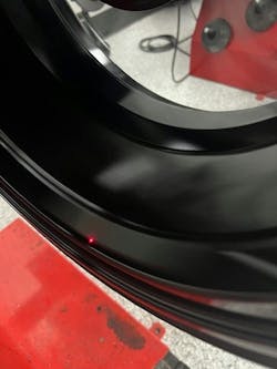
Rim runout can be measured in two different ways, depending on the balancer being used. Some models can measure a bare rim using lasers and cameras. This is a preferred method since the tire does not block the bead seat of the rim. The bead seat is the most critical surface measurement and is referenced off the hub center and hub face. Any radial or lateral movement in the bead seat in relation to the hub center and face will be transferred into the tire bead, sidewall and tread surface, potentially causing imbalance concerns.
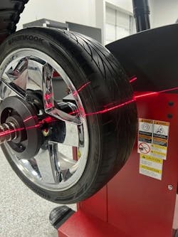
Another method involves measuring the inner surface of the rim with the tire still mounted, using a laser and camera to profile the rim, and counting the number of spokes and weight placement locations. This method accurately measures the bead seat area where tape weights would be applied. This method is accurate since a rim is usually bent or warped the same on the inside as on the outside. Again, any rim irregularity will transfer into the tire and the road. Most new alloy rims will have some runout (0.000 to 0.006 of an inch). According to OEM service information, when runout exceeds 0.030 inches, it's time to consider repair or replacement. Regardless of the measurement method used, it’s important to note the low point, average and high point on the rim.
Radial force vectoring: Radial force vectoring (RFV) is the force that is applied to the road due to an out-of-round tire assembly. With HP and UHP tires, these forces can be transmitted in greater amounts due to the tire’s construction, which provides superior braking and lateral acceleration. Unlike rim runout, there is only one way to obtain the measurements required to calculate RFV: the tire must be mounted to the rim.
To calculate RFV, the radial or vertical runout of the tire assembly is measured. Depending on the balancer, a laser and camera or multiple cameras and lasers are used to measure the radial runout of the tire and the dimensional profile of the tire. This measurement serves two purposes.
One is to calculate the RFV using the runout in thousandths of an inch. An algorithm considers the tire size, profile, aspect ratio and tire pressure to calculate all of this data. A number is then output, in pounds of force, that the tire assembly will exert on the road surface during each rotation. This number is used by the installer in conjunction with the tire manufacturer. When tire runout or RFV is measured, the machine will plot three different measurements: first order or one high point (resembling an egg), second order or two high points (resembling a football) and third order, three high points (resembling a three-cornered hat). While the second and third orders provide additional information, the first order high point is the important measurement.
The second and most useful measurement to the installer is simply the runout measurement. This measurement, along with rim runout, is used to match the tire to the rim. More on that will be discussed in tire indexing.
Lateral force: Lateral force is the force exerted by the tire in a left or right direction. This force may be more noticeable in HP and UHP tires due to their construction and profile. Tire conicity can be a cause of these forces. Think of rolling a paper cup across a table. It rolls in one direction. The cup is at an exaggerated angle, but even an almost imperceptible angle working on a low-profile, high-grip tire can have an effect on vehicle direction. As mentioned before, multi-camera and laser machines look at the tire profile, aspect ratio, width and diameter across the entire tread surface, sidewalls and rim. This data is used to determine the best tire assembly placement on the vehicle to minimize tire lateral force affect. If this advanced measuring is not available, try swapping the tire assemblies across the front axle on non-directional tires. Swap the tires on the rims if they are directional.
Tire indexing: Tire indexing is simply ensuring that the tire and rim assembly (the wheel) is as round as possible. No tire is perfect. Imagine a wheel assembly slightly resembling an egg shape. Each time the high point makes contact with the road, it tries to press the tread into the road surface. Since the road won’t budge, the axle/spindle is pushed upward. The greater the magnitude of the high point, the greater the force exerted on the road (or amplitude). This high point generates a frequency linked to the assembly’s rotational speed or revolutions per second (hertz). This phenomenon mirrors the impact of an imbalanced wheel assembly on the vehicle. Many vehicles are sensitive to tire frequencies between 12 Hz and 17 Hz, provided the amplitude is great enough. This is where an adequately balanced assembly can still cause vibrations in the vehicle.
Earlier we discussed rim imperfection. Tire indexing is where this measurement of rim runout comes into play. Now, we can use this understanding of rim imperfection to our advantage. If a wheel assembly has an average high point measuring 0.030 of an inch high and a rim with a low point measuring 0.015 of an inch low, we can rotate the tire on the rim. By aligning the high point with the low point during indexing, we reduce the assembly’s runout by 50%. This indexing decreases the overall runout and consequently reduces the amplitude exerted on the vehicle axle/spindle. This might be enough reduction in amplitude to address a vibration concern. However, in the case of an HP or UHP tire with a low profile and high lateral force capabilities, the internal tire structure could potentially amplify the force that is generated. Conversely, if the rim exhibits minimal runout while the tire has a lot, there may be no feasible solution and the tire may need to be replaced.
Static balance: There are two types of balancing — actually, measuring — that modern-day tire balancers perform: dynamic balance and static balance. Dynamic balance implies the assembly is in motion, while static balance suggests it is stationary. However, modern balancers spin the assembly to measure the force generated by the imbalance making all balancing essentially dynamic. What is being measured are two plane (dynamic) and single plane (static) imbalance/force. There are basically three parameters the balancer needs to calculate the weight required to counter the imbalance and its placement: the size of the circle where the weight will be placed, the distance between weight placement planes and the spinning speed (rpm) of the assembly.
The balance method used on HP and UHP wheel assemblies is always dynamic (two-plane), the most common type of balancing. Once the assembly is mounted to the machine and proper tooling centering and lateral positioning are confirmed, the balancer spins the assembly. The indicated weight amounts and placements ensure a balanced assembly - typically within less than one-fourth of an ounce. This is due to the rounding off done by all machines, typically around 0.30 ounce. This prevents ‘chasing weights,’ since one-fourth of an ounce is usually the smallest available weight. Most machines will have some type of non-round off function for those who want a zero balance. While dynamic balance is usually sufficient, concerns such as a little nibble in the steering wheel, floorboard or seat may still arise and this can be addressed by static balance.
Static balance, alternatively referred to as residual static balance, is the result of the imbalance remaining after completing the two planes of dynamic balance. Whether dynamic balance is done first or not, the balancer has already calculated the placement of static (single plane) weight based on force measurements, knowing the static plane location on the assembly. To achieve the optimal balance, addressing this residual static balance is essential. Typically, a small amount of weight (one-fourth of an ounce) is required, placed at the center mass of the assembly. Since it will be positioned toward the rim's center, a tape-on weight is necessary. The static balance is critical because it has a major influence on the vertical motion of the assembly, particularly affecting the spindle/axle. Given the low-profile and performance-based design of HP and UHP tires, even a small amount of static imbalance can profoundly affect ride comfort.
