SUBJECT VEHICLES: 2007-2013 GMC Sierra and Yukon.
RELEARN PROCEDURE? Yes.
SPECIAL TOOLS NEEDED? A TPMS Sensor Activation Tool (EL-46079 or EL-50448) may be used.
The tire pressure monitoring system (TPMS) on the 2007-2013 GMC Sierra and Yukon alerts the driver when any one or all four of the vehicle’s tire pressures have become significantly under-inflated.
The system also will display individual tire pressures and their locations on the driver information center (DIC). The TPMS uses the powertrain control module (PCM) or body control module (BCM), instrument panel cluster (IPC), DIC, remote control door lock receiver (RCDLR), a radio frequency (RF) transmitting pressure sensor in each wheel/tire assembly, and the serial data circuit to perform the system functions. When the vehicle is stationary, the sensors go into stationary mode.
In this mode, the sensors transmit once every 60 minutes to minimize sensor battery consumption. As vehicle speed increases to 20 mph (32 km/h), the sensors go into drive mode, in which they transmit once every 60 seconds.
NOTE: The sensor’s pressure accuracy is about 2 psi (14 kPa) at temperatures from 14 to 158 degrees Fahrenheit (-10 to 70 degrees Celsius). The RCDLR receives and translates the data contained in each sensor transmission, then sends the tire pressure and tire location data to DIC for display. When the TPMS detects a significantly under-inflated tire pressure, a “CHECK TIRE PRESSURE” message is displayed on the DIC and the low tire pressure indicator is displayed on the IPC. This DIC message will also set if a spare tire is in use. The RCDLR has the ability to detect malfunctions within the TPMS. Any malfunctions detected will cause the DIC to display a “SERVICE TIRE MONITOR” warning message.
Tire pressure monitor warning indicators
When the TPMS detects a significant loss of tire pressure, the “CHECK TIRE PRESSURE” message is displayed on the DIC and the low tire pressure indicator is displayed on the instrument panel. Both the message and indicator can be cleared by adjusting the tires to their recommended pressures. The DIC will display the “SERVICE TIRE MONITOR” message if one or more of the tire pressure sensors has malfunctioned or if all of the sensors have not been programmed successfully. If warning indicators are still on after a completed relearn procedure, there is a problem in the TPMS.
Reset procedures
NOTE: When the wheels have been rotated, or a tire pressure sensor or RCDLR has been replaced, retrain the tire pressure sensor. When the TPMS detects a significant loss of tire pressure, the “CHECK TIRE PRESSURE” message is displayed on the DIC and the low tire pressure indicator is displayed on the instrument panel. Both the message and indicator can be cleared by adjusting the tires to their recommended pressures.
Tire pressure sensor relearn
NOTE: Once the learn mode has been enabled, each of the sensor’s unique Identification (ID) codes can be learned into the RCDLR’s memory. When a sensor’s ID has been learned, the RCDLR sends a serial data message to the BCM to sound a horn chirp. This verifies the sensor has transmitted its ID, and the RCDLR has received and learned it.
NOTE: Each sensor takes a pressure measurement sample once every 30 seconds while in stationary mode. If the tire pressure increases or decreases by more than 1.6 psi (11 kPa) from the last pressure measurement, another measurement will occur immediately to verify the change in pressure. If a pressure change has indeed occurred, the sensor transmits in learn mode. When the RCDLR receives a learn mode transmission while in learn mode, it will assign that sensor ID to the location on the vehicle relative to the order in which it was learned. The RCDLR must learn the sensor ID codes in the proper sequence in order to determine sensor location. The first learned ID is assigned to left front, the second to right front, the third to right rear and fourth to left rear.
NOTE: The TPMS will cancel the learn mode if more than two minutes have passed and no sensors have been learned, or if the system has been in learn mode for more than five minutes. If the learn mode is canceled before any sensor has been learned, the RCDLR will remember all current sensor IDs and their locations. As soon as the first sensor ID code is learned, all other IDs are erased from the RCDLR’s memory. The updated tire pressures will not be displayed on the DIC until RCDLR receives two more valid transmissions from each sensor.
After performing the procedure below, always test drive the vehicle above 25 mph for at least two minutes before viewing tire pressures on the DIC.
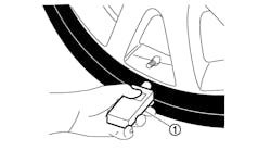
NOTE: In the following procedure, a TPMS Sensor Activation Tool (EL-46079 or EL-50448) may be used in place of increasing/decreasing pressures to enable the sensor. To use, place the activator antenna against the tire sidewall close to the wheel rim at the valve stem location, then press and release the ACTIVATE button.
NOTE: If a TPMS Sensor Activation Tool (EL-46079 or EL-50448) is used, and the vehicle is having trouble entering the relearn mode, check the batteries in the activation tool. Low batteries may allow some functions to work, but not allow the vehicle to perform the learn function. When the internal battery is fresh (fully charged), the indicator is “full” or is all dark. When the battery is depleted, the indicator shows “empty” or is all light.
There are three ways to enable the learn mode; using a scan tool, using the keyless entry transmitters (if equipped) or using the DIC. After the learn mode has been enabled there are two different methods of activating the transmitters in the tires; utilizing the J-46079 tire pressure monitor diagnostic tool at each tire or increase/decrease tire pressure for eight to 10 seconds in each tire. If a scan tool has been used to enable the learn mode, the J-46079 must be used to activate the transmitters.
NOTE: Before proceeding with the following steps, ensure that no other sensor learn procedure is being performed simultaneously, or that tire pressures are not being adjusted on a TPMS-equipped vehicle within close proximity.
Preferred scan tool method
IMPORTANT: In the event a particular sensor’s information is displayed on the special tool upon activation but the horn does not chirp, it may be necessary to rotate the wheel valve stem to a different position because the sensor signal is being blocked by another component.
1) Using a scan tool, initiate the TPMS learn mode. A double horn chirp will sound indicating the learn mode has been enabled. The left front turn signal also will be illuminated.
2) Starting with the left front tire, active the sensor by holding the antenna of the Sensor Activation Tool aimed upward against the tire sidewall close to the wheel rim at the valve stem location. Press and release the Activate button and wait for a horn chirp. Once the horn chirp has sounded, the sensor information is learned and the turn signal in the next location to be learned will illuminate.
3) After the horn chirp has sounded and the right front turn signal is illuminated, repeat the procedure for the remaining three sensors in this order: right front, right rear, left rear.
4) When the left rear sensor has been learned and a double horn chirp has sounded, the learn process is complete and the RCDLR exits the learn mode.
5) Turn ignition OFF, adjust all tires to the recommended pressures.
Alternate keyless entry transmitter or DIC method
NOTE: If the learn mode cannot be enabled, the TPMS is not enabled in RCDLR. See appropriate service information.
1) With the ignition ON, initiate the TPMS learGMCn mode using one of the following procedures:
- On vehicles equipped with keyless entry, simultaneously press the keyless entry transmitter’s lock and unlock buttons until a double horn chirp sounds indicating the learn mode has been enabled. The left front turn signal also will be illuminated.
- On vehicles not equipped with keyless entry, press and release the DIC INFO button until the TIRE LEARN message appears on the DIC display. Press and hold the SET/RESET button until a double horn chirp sounds indicating the learn mode has been enabled. The left front turn signal also will be illuminated.
NOTE: If a horn chirp does not sound after 35 seconds for any of the four sensors, turn the ignition switch to the OFF position to exit the learn mode. Repeat the procedure from the first step.
2) If using the Sensor Activation Tool, go to Step 2 of the Preferred procedure above. If using the increase/decrease tire pressure method, go to the next step.
3) Starting with the left front tire, increase or decrease the pressure for eight to 10 seconds, or until a horn chirp sounds. The horn chirp may occur before the eight to 10 second pressure increase/decrease time period has been reached, or up to 30 seconds after the eight to 10 second pressure increase/decrease time period has been reached. Once the horn chirp has sounded, the sensor information is learned and the turn signal in the next location to be learned will illuminate.
4) After the horn chirp has sounded, repeat the procedure for the next three sensors in the following order: right front, right rear, left rear.
5) After the left rear sensor has been learned, a double horn chirp will sound. Turn the ignition switch to the OFF position to exit the relearn procedure. Adjust all tire pressures to specification. If the double horn chirp did not occur, repeat the procedure from the first step.
Demounting/mounting procedures
CAUTION: The tire should be demounted from the wheel using the tire changer manufacturer’s instructions. Use the following information to avoid damage during the demounting/mounting procedures.
NOTE: If the vehicle’s tires are replaced with those not having a TPC Spec number, the TPMS may give an inaccurate low pressure warning. Non-TPC Spec tires may give a low pressure warning that is higher or lower than the proper warning level achieved by TPC Spec numbered tires.
NOTE: When the wheels have been rotated, or a tire pressure sensor or RCDLR has been replaced, retrain tire pressure sensor. See Reset procedures.
Tire pressure sensor
CAUTION: Do not inject any tire liquid or aerosol tire sealant into the tires, as this may cause a malfunction of the tire pressure sensors. If any tire sealant is noted upon tire demounting, replace the sensor. Also remove all residual liquid sealant from the inside the tire and wheel surfaces.
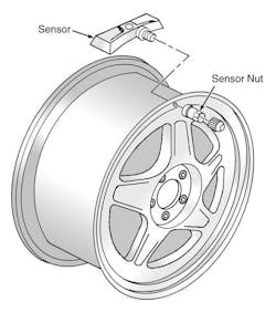
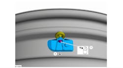
There are currently two different kinds of TPMS sensors in use on the vehicles covered in this article. Identification of which sensor is in use can easily be made after the tire has been removed from the wheel by referring to Figures 1 and 2.
Removal and installation
1) Raise the vehicle on a suitable support. Remove the tire/wheel assembly from the vehicle.
2) Demount the tire from the wheel following the tire changer manufacturer’s instructions while paying special attention to the following to avoid damaging the tire pressure sensor:
- Place the sensor’s cap and valve on a dry, clean surface after removal. The cap is aluminum and the valve is nickel-plated to prevent corrosion. DO NOT substitute a cap or valve made of any other material.
- Position the bead breaking fixture 90 degrees from the valve stem when separating the tire bead from the wheel.
- Position the mounting/demounting head so the tire iron (or pry bar) can be inserted slightly clockwise of the sensor body when prying the tire bead up and over the mounting/demounting head.
- Using the tire machine, rotate the tire/wheel assembly clockwise when transferring the tire bead to the outside of the wheel rim.
- Repeat the steps for the inner bead.
3) If the TPMS sensor is the clamp-in style (see Figure 1), follow clamp-in style removal as follows. If it is a snap-in style (see Figure 2), follow the snap-in style removal below.
Clamp-in style sensor removal
1) Remove the tire pressure sensor nut (see Figure 1).
2) Remove the sensor from the wheel hole.
3) Remove the sensor grommet from the valve stem.
4) Follow the clamp-in sensor installation below, to replace the sensor.
Snap-in style sensor removal
1) Remove the TORX screw (3) from the tire pressure sensor (2) and pull it straight off the tire pressure valve stem (1) (see Figure 2).
2) Remove the tire pressure valve stem by pulling it through the rim.
3) Follow snap-in style sensor installation below, to replace the sensor.
Clamp-in sensor installation
1) Clean any dirt or debris from the grommet sealing areas. Install the grommet on the sensor valve stem.
2) Insert the sensor in the wheel hole with the air passage facing away from the wheel.
3) Install the sensor nut, and position the sensor body parallel to the inside wheel surface while tightening the nut to 62 in.-lbs. (7 N.m).
4) Before installing the tire on the wheel, note the following items to avoid tire pressure sensor damage upon tire mounting:
- Position the mounting/demounting head 180 degrees from the valve stem.
- Position the bead transition area 45 degrees counterclockwise of the valve stem.
- Using the tire machine, rotate the tire/wheel assembly clockwise when transferring the tire bead to the inside of the wheel rim.
- Repeat the steps for the outer bead.
5) Install the tire on the wheel. Install the tire/wheel assembly on the vehicle. Retrain the tire pressure sensor. See Reset procedures.
NOTE: A service replacement tire pressure sensor is shipped in the OFF mode. In this mode, the sensor’s unique identification code cannot be learned into the RCDLR’s memory.
The sensor must be taken out of the OFF mode by spinning the tire/wheel assembly above 20 mph (32 km/h) for at least 10 seconds in order to close the sensor’s internal roll switch.
Snap-in style sensor installation
1) Assemble the tire pressure sensor (2) to the valve stem and install the new TORX screw (3) — see Figure 2.
2) Apply tire soap to the rubber portion of the valve stem.
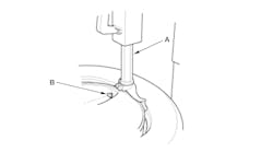
3) Using a tire valve stem mounting tool, pull the valve stem through in a direction parallel to the valve hole on the rim (see Figure 3).
4) Before installing the tire on the wheel, note the following items to avoid tire pressure sensor damage upon tire mounting:
- Position the mounting/demounting head 180 degrees from the valve stem.
- Position the bead transition area 45 degrees counterclockwise of the valve stem.
- Using the tire machine, rotate the tire and wheel assembly clockwise when transferring the tire bead to the inside of the wheel rim.
- Repeat these steps for the outer bead.
5) Install the tire on the wheel. Install the tire/wheel assembly on the vehicle. Retrain the tire pressure sensor. See Reset procedures. NOTE: Snap Fit TPMS sensors are still shipped in the OFF mode. However, the TPMS sensor no longer needs to be spun to remove it from the OFF mode. The sensor will exit its OFF state when the tire is inflated. The technician can then program the vehicle as normal. ■
TORQUE SPECIFICATIONS
Component
Ft.-lbs. (N.m)
Spare tire hoist retaining bolt 30 (40)
Wheel nut 140 (190)
In.-lbs. (N.m)
Clamp-in sensor nut 62 (7)
Snap-in sensor TORX screw 11.5 (1.3)
Information for this column comes from Mitchell 1’s “Tire Pressure Monitoring Systems Guide” for domestic and import vehicles.
For more information, visit www.mitchell1.com.
To read more TPMS articles, see:


