DESCRIPTION and OPERATION
During driving, the TPMS system receives the signal transmitted from the tire pressure sensor installed in each wheel. The body control module (BCM) of this system has pressure judgment and trouble diagnosis functions. When the TPMS system detects low inflation pressure or another unusual symptom, the low tire pressure warning lamp in the combination meter comes on.
Tire pressure varies as per the change in tire temperature. If the tire pressure is less than the warning tire pressure value, the low tire pressure warning lamp illuminates.
Location of wheel is specified due to the synchronism of wheel sensor position and tire pressure sensor position.
The TPMS system is activated when the vehicle speed is 25 mph (40 km/h) or more.
The TPMS system has Easy Fill Tire Alert function to aid in tire inflation.
ID REGISTRATION PROCEDURE
Work Procedure
TPMS ID registration can be performed using one of the following procedures:
- Transmitter Activation tool [KV48105501 (J-45295-A) ] using CONSULT (preferred method)
- Signal Tech II tool [- (J-50190) ] using CONSULT (preferred method)
- Signal Tech II tool [- (J-50190) ] without CONSULT
- CONSULT only
TPMS REGISTRATION WITH TRANSMITTER ACTIVATION TOOL — KV48105501 (J-45295-A)
1.) Ignition switch ON.
2.) Select "Work support" mode of "BCM (AIR PRESSURE MONITOR). " Then, select "ID REGIST."
3.) Select "Start" on "ID REGIST" screen.
4.) Hold the transmitter activation tool, KV48105501 (J-45295-A), against the side of the left front tire, near the valve stem.
5.) With the tool held at a 0 to 15 degree angle to the tire, press and hold the transmitter activation tool button until the indicator lamp turns OFF (approximately five seconds).
6.) Repeat steps four and five for the remaining tires in this order: right front, right rear and left rear.
7.) When ID registration is complete, check the following pattern at each wheel: Front LH, Front RH, Rear RH, Rear LH. (Two blinks of the turn signal lamp. Green on CONSULT indicates done.)
8) After the ID registration procedure for all wheels is complete, select "End" to finish ID registration.
9) Test drive the vehicle to ensure that the TPMS lamp is OFF and no warning messages are present.
TPMS REGISTRATION WITH SIGNAL TECH II TOOL — J-50190
1.) Adjust the tire pressure for all tires to the recommended value.
2.) Ignition switch ON.
3.) Select "Work support" mode of "BCM (AIR PRESSURE MONITOR). " Then, select "ID REGIST."
4.) Select "Start" on "ID REGIST" screen.
5.) Turn on the Signal Tech II tool (J-50190).
6.) Hold the Signal Tech II against the side of the left front tire, near the valve stem.
7.) With the tool held at a 0 to 15 degree angle to the tire, select "Activate Sensor" from the main menu, then press and release the "OK" button to activate the sensor. Once the sensor is activated, the vehicle parking lamps will flash and the sensor ID will appear on the CONSULT screen.
8.) Repeat steps 6 and 7 for the remaining tires in this order: right front, right rear and left rear.
9.) When ID registration is complete, check the following pattern at each wheel: Front LH, Front RH, Rear RH, Rear LH.
10.) Once all sensors have been activated, select "End" to finish ID registration.
11.) Test drive the vehicle to ensure that the TPMS lamp is OFF and no warning messages are present.
TPMS Registration With Signal Tech II Tool (J-50190) without CONSULT
1.) Adjust the tire pressure for all tires to the recommended value.
2.) Turn on the Signal Tech II tool (J-50190) and select "TPMS Check" from the main menu.
3.) Select vehicle model and year.
4.) When prompted, hold the Signal Tech II against the side of the left front tire, near the valve stem.
5.) With the tool held at a 0 to 15 degree angle to the tire, press and release the "OK" button to activate the sensor. Once the sensor is activated, the tool will sound a tone and the tire pressure will be displayed.
6) Repeat steps four and five for the remaining tires in this order: right front, right rear and left rear.
7) When prompted, connect the tool to the data link connector. The tool will connect to the BCM, read the VIN, read sensor IDs and check for TPMS DTCs. Along with DTCs detected, one of the following will be displayed next to each wheel:
- N/A - Not applicable because no ID found by the tool
- OK - Wheel and sensor are in original position
- NEW - New ID found compared to BCM
- RT - Wheel has been rotated
- Low Press - Low tire pressure
8.) If no DTC is present or the repair has been completed, press the "OK" button to register the IDs and clear DTCs.
9.) Test drive the vehicle to ensure that the TPMS lamp is OFF and no warning messages are present.
10.) Print a Signal Tech II Audit Report for your records. Refer to the Signal Tech II User Guide for instructions.
TPMS REGISTRATION WITH CONSULT ONLY
1.) Adjust the tire pressure for all wheels to match this list: Front LH 35 psi, Front RH 32 psi, Rear RH 29 psi, Rear LH 26 psi
2.) Ignition switch ON.
3.) Select "Work support" mode of "BCM (AIR PRESSURE MONITOR) ". Then, select "ID REGIST."
4.) Select "Start" on "ID REGIST" screen.
5.) Drive the vehicle at a speed greater than 25 mph(40 km/h) for three minutes or more.
6.) After ID registration for all wheels is complete, select "End" to finish ID registration.
7.) Adjust the tire pressures for all tires to the recommended value.
8.) Test drive the vehicle to ensure that the TPMS lamp is OFF and no warning messages are present.
TIRE PRESSURE SENSOR REMOVAL AND INSTALLATION
WHEEL AND TIRE
Removal and Installation
REMOVAL
1.) Remove wheel cover (if equipped).
2.) Remove wheel nuts using power tool.
3.) Remove wheel and tire.
CAUTION:
- When installing wheel nuts, tighten them diagonally by dividing the work two or three times in order to prevent the wheels from developing any distortion.
- Be careful not to tighten wheel nuts to a torque exceeding the specification to prevent strain on the disc brake rotor or brake drum.
- Use Genuine NISSAN wheel nuts.
TIRE PRESSURE SENSOR
Removal and Installation
REMOVAL
1.) Remove the wheel and tire.
2.) Remove the valve cap and the valve core to deflate the tire.
CAUTION:
- Do not use silicone lubricant. Use of silicone lubricant will deteriorate the tire and wheel.
- Do not damage the wheel.
3.) Lubricate the tire outside bead well with a suitable non-silicone lubricant and separate the tire outside bead from the wheel.
4.) Lubricate the tire inside bead well with a suitable non-silicone lubricant and separate the tire inside bead from the wheel.
5.) Carefully lift and set the wheel and tire onto the tire changer turntable so that the tire pressure sensor is at the bottom. Position the wheel and tire so that the tire pressure sensor is 270 degrees from the mounting/demounting head.
6.) Remove the tire from the wheel.
CAUTION: Do not drop or strike the tire pressure sensor. Replace the tire pressure sensor if it has been dropped from higher than one meter.
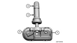
7.) Remove the screw and the tire pressure sensor from the valve.
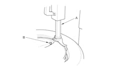
8.) Cut the inner end (A) of the valve using a suitable tool (B).
9.) Remove the valve (2) from the wheel (1) using Tool (A).
INSTALLATION
Make sure there are no burrs, foreign substances, or indications of damage to the wheel.
1.) Clean the valve hole in the wheel.
CAUTION:
- Do not use silicone lubricant. Use of silicone lubricant will deteriorate the tire and wheel.
- Do not allow lubricant to contact the air pressure detection hole (B).
2.) Apply a suitable non-silicone lubricant to the surface of the valve (A) that touches the wheel and to the valve hole in the wheel.
3.) Remove the valve cap from the new tire pressure sensor unit.
- Do not damage the tire pressure sensor.
- Do not allow lubricant to contact the air pressure detection hole (B).
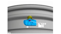
- The tire pressure sensor must be oriented tangentially to the rim of the wheel.
4.) Position the valve (C) in the valve hole in the wheel (A).
CAUTION:
- Do not drop or strike the tire pressure sensor. Replace the tire pressure sensor if it has been dropped from higher than one meter.
- Do not damage the wheel.
- Install the valve all the way into the wheel.
- Make sure the valve seats properly in the valve hole in the wheel.
- If the tire pressure sensor unit position is not correct, rotate the tire pressure sensor unit to the correct position using Tool.
5.) Install the valve (2) to the wheel (1) using Tool (A).
6.) Apply a suitable non-silicone lubricant to the tire inside bead.
Do not damage the wheel or the tire pressure sensor.
Do not allow the tire beads to make contact with the tire pressure sensor.
7.) Install the tire inside bead (1) onto the wheel (2) in the position shown, below. Do not touch the tire pressure sensor with the mounting head.
8.) Place the wheel on the turntable of the tire machine. Make sure that the tire pressure sensor (1) is 270 degrees from the mounting/dismounting head (2).
9.) Apply a suitable non-silicone lubricant to the tire outside bead.
When installing, make sure that the tire does not rotate relative to the wheel.
NOTE:
- If the tire is being reused, align the matching mark applied on the tire with the position of the valve hole in the wheel for the purpose of wheel and tire balance adjustment after installation.
- To avoid damage to vehicle, the tire must not slip or spin on the wheel when demounting, or mounting a tire's outer bead. Damage to the wheel or the tire pressure sensor could result.
10.) Install the tire outside bead onto the wheel as normal.
11.) Inflate the tire.
12.) Install the valve cap.
13.) Balance the wheel and tire.
14.) Install the wheel and tire in the appropriate position on the vehicle.
15.) When replacing the tire pressure sensor, the ID registration procedure must be performed.
Disposal
CAUTION:
- When discarding tire pressure sensor, remove battery from tire pressure sensor and dispose of battery according to the law and local regulations.
1.) Remove battery (1) from tire pressure sensor.
2.) Remove urethane from tire pressure sensor.
3.) Using a suitable tool, cut battery terminal (A), then remove battery from tire pressure sensor.


