The tire pressure monitoring system (TPMS) of the 2011-2019 Ford/ Lincoln MKT monitors the air pressure in the four road tires with wheel-mounted tire pressure sensors.
The sensors transmit radio frequency signals to the smart junction box (SJB), or BCM in later models, approximately every 60 seconds when the vehicle speed exceeds 20 mph (32 km/h).
If the vehicle is stationary for more than 30 minutes, the sensor will enter into a “sleep mode” and stop transmitting.
Each tire pressure sensor transmission is compared against a low-pressure limit (the pressure listed on the vehicle certification label minus 25%, which will be about 6 to 9 psi).
If it is determined that the tire pressure has fallen below this limit, the SJB sends a message to the instrument cluster, which then illuminates the low pressure warning indicator and displays the appropriate message(s) in the message center (if equipped).
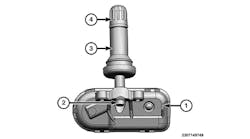
All tire pressure sensors are battery operated. The sensors are attached to the portion of the valve stem located inside the wheel with a T10 Torx screw. Under the following conditions, the TPMS may not function properly:
• Low tire pressure.
• Tire pressure sensor is missing or damaged.
• Spare tire is installed as a road wheel.
• Incorrect tire pressure sensor is installed.
• Tire pressure sensor installed incorrectly.
• Non-OEM wheels installed (aftermarket rims).
• Non-OEM equipped run-flat tires installed.
• Other non-OEM modifications (roll cages, service barriers, part racks, ladder racks, etc.)
TIRE PRESSURE MONITOR WARNING INDICATORS
NOTE: As ambient temperature decreases by 6 degrees Celsius (10 degrees Fahrenheit),
tire pressure decreases 1 psi (7 kPa). Because tire pressures fluctuate with temperature changes, tire pressures must be set when the tires are at outdoor ambient temperatures.
If not the tire pressure may drop enough to be detected by the TPMS, which will activate the low pressure warning light.
When the tire pressure warning light comes on solid and the message center displays “LOW TIRE PRESSURE,” check the air pressure of all tires and adjust to the specified cold pressure listed on the vehicle certification label (found on the driver’s door or door pillar). Drive the vehicle at 20 mph (32 km/h) for at least two minutes. If the vehicle has been stationary for more than 30 minutes, the sensor will enter into a “sleep mode” and stop transmitting. A TPMS sensor activation procedure may be needed. Make sure the warning light goes off. If the warning light stays on, there is a malfunction in the TPMS. See the appropriate manufacturer service information.
When the tire pressure warning light flashes for 70 seconds and then remains illuminated, after a bulb-check has been performed and the message center displays warning messages, there is a malfunction in the TPMS. See the appropriate manufacturer service information.
TPMS RESET PROCEDURES
NOTE: If a tire pressure sensor is replaced, it will need to be trained. If the vehicle has different front and rear tire pressures, the tire pressure has to be adjusted and the TPMS sensors have to be trained. If the vehicle has the same tire pressure on the front and rear tires, the tire pressure monitoring system is not affected by wheel and tire rotation.
When the tire pressure warning light comes on solid and message center displays “LOW TIRE PRESSURE,” check the air pressure of all tires and adjust to the specified cold pressure listed on the vehicle certification label (found on the driver’s door or door pillar). Drive the vehicle at 20 mph (32 km/h) for at least two minutes. The TPMS sensor activation procedure may also be used in place of driving. See TIRE PRESSURE SENSOR ACTIVATION. Make sure the warning light goes off.
TIRE PRESSURE SENSOR TRAINING
NOTE: In the following procedure, TPMS Activation Tool (204-363) must be used.
NOTE: The tire pressure sensor training procedure must be done on a single vehicle, in an area without radio frequency (RF) noise and at least 3 ft. (1 m) away from any other vehicle equipped with a TPMS system. RF noise is generated by electrical motor and appliance operation, cellular telephones and remote transmitters, power inverters and portable entertainment equipment.
NOTE: A new tire pressure sensor is shipped in an OFF mode (or battery saver mode) and must be turned ON before it can be trained. To turn the sensor on, inflate the tire to the recommended inflation pressure and wait at least two minutes, then continue with the sensor training procedure.
1) Turn the ignition switch to the OFF position, then press and release the brake pedal.
2) Turn the ignition switch from the OFF position to the RUN position three times, ending in RUN position. Do not wait more than one minute between each key cycle.
3) Press and release the brake pedal.
4) Turn the ignition switch to the OFF position.
NOTE: The horn will sound once and the tire pressure warning light will flash if the train mode has been entered successfully (if equipped, the message center displays “TRAIN LF TIRE”).
5) Turn the ignition switch from the OFF position to the RUN position three times, ending in RUN position. Do not wait more than one minute between each key cycle.
NOTE: It may take up to six seconds to activate a tire pressure sensor. During this time, the activation tool must remain against the sidewall of the tire.
NOTE: If a sensor does not respond to the activation tool, attempt to activate the same sensor using the activation tool. If the sensor still does not respond, move the vehicle to rotate the wheels at least 1/4 of a turn and attempt to activate the same sensor again.
NOTE: If the SJB does not recognize any one of the four tire pressure sensors during the two minute time limit for each sensor response, the horn will sound twice and the message center (if equipped) will display “TIRE NOT TRAINED REPEAT.” The training procedure must be repeated from the beginning.
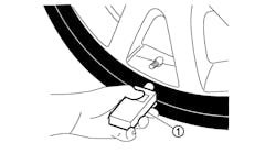
6) Place the TPMS activation tool (204-363) on the left front tire sidewall at the tire valve stem. Press the test button on the activation tool. The horn will sound briefly to indicate that the tire pressure sensor has been recognized by the SJB.
NOTE: Do not wait more than two minutes between training each sensor. If the wait time is more than two minutes the SJB will stop and the training procedure must be repeated from the beginning.
7) Within two minutes after the horn sounds, place the activation tool on the right front tire sidewall -180 degrees from the valve stem for strap and cradle type sensors or at the valve stem for valve stem-mounted sensors. Repeat the procedure for the right rear and left rear tires, in that order.
8) When the tire training procedure is complete, the message center (if equipped) will display “TIRE TRAINING COMPLETE.”
For vehicles not equipped with a message center, successful completion of the training procedure will be verified by turning the ignition switch to the OFF position without the horn sounding. If the horn sounds twice when ignition is turned off, the training procedure was not successful.
TIRE PRESSURE SENSOR ACTIVATION
1) Turn ignition switch to the ON position.
2) Place the activation tool on the left front tire sidewall at the tire valve stem.
NOTE: A green light will flash and a beep sound on the activation tool for each successful TPMS sensor response.
3) Press the test button on the activation tool to activate the TPMS sensor. For best results, activate each sensor twice.
NOTE: If, after adjusting tire pressures and activating sensors, the tire pressure warning light is still illuminated, there is a malfunction in the TPMS. See the appropriate manufacturer service information.
4) Repeat procedure for each remaining tire.
DEMOUNTING/MOUNTING PROCEDURES
CAUTION: The tire should be demounted from the wheel using the tire changer manufacturer’s instructions. Use the following information to avoid damage during the demounting/mounting procedures.
CAUTION: The tire and wheel must always be correctly matched. It is very important to determine the size of each component before any assembly operations commence. Failure to adhere to these instructions can result in an explosive separation and cause serious bodily injury or death.
CAUTION: Use only wheels and wheel nuts that have been designed for the current model year. Tire pressure sensors are not designed to be used with aftermarket wheels. Aftermarket wheels or wheel nuts may not fit or function correctly and can cause personal injury or damage to the vehicle. A wheel and tire assembly equipped with tire pressure sensor will have the following verbiage stamped or cast on the wheel: “Sensor May Be Inside.”
CAUTION: Tighten wheel nuts in a star pattern. Failure to follow tightening specifications may result in high brake disc runout, serious injury or death.
NOTE: If possible, use a digital tire gauge (Ford Part #204-354, for example) any time tire pressures are measured to be sure that accurate values are obtained. Ford recommends the use of a digital or dial type tire pressure gauge rather than a stick type gauge for increased accuracy.
TIRE PRESSURE SENSOR
CAUTION: This vehicle is equipped with valve-mounted tire pressure sensors. Valve-mounted and strap-mounted tire pressure sensors are not compatible. Swapping wheels from one vehicle to another with the different systems will adversely affect TPMS operation.
Removal
1) Remove the wheel and tire.
NOTE: The valve stem is connected to the TPMS sensor. Do not pull the valve stem from the wheel, or damage to the sensor will occur.
2) Remove the valve stem core and fully deflate all tires.
3) Remove the tire from the wheel following the tire manufacturer’s directions.
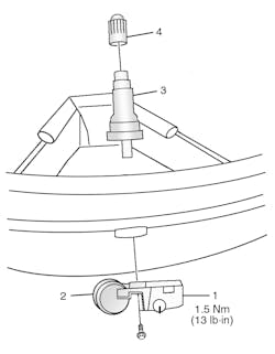
4) Remove the TPMS sensor from the valve in the following sequence (see Figure 1). Using a T10 Torx, remove the valve stem-to-TPMS sensor screw. Carefully and firmly, pull the sensor straight down and separate it from the valve stem.
NOTE: A new valve stem must be installed whenever a new tire or wheel is installed. When installing a new wheel, always install a new valve stem and reuse the TPMS sensor from the previous wheel if possible. The TPMS will not have to be trained if the sensor is reused.
5) Using a suitable valve stem puller and a wood block, remove the valve stem from the wheel.
6) If the TPMS sensor is being reused, inspect the TPMS sensor for damage and install new parts as necessary.
Installation
NOTE: To prevent the TPMS sensor and valve stem damage, the valve stem must be installed onto the TPMS sensor and then installed into the wheel as an assembly.
1) Install a new valve stem onto the TPMS sensor tightening the valve stem-to- TPMS sensor screw to 13 in.-lbs. (1.5 Nm).
NOTE: It is important to pull the valve stem and the TPMS sensor assembly through the wheel rim hole in a direction parallel to the valve stem hole axis. If the assembly is pulled through at an angle, damage to the valve stem and sensor assembly may occur.
NOTE: Use only a suitable fast-drying, corrosion-inhibiting tire bead lubricant to lubricate the tire. Use of anything other than tire bead lubricant may result in damage to the TPMS sensor.
2) Lubricate the valve stem with suitable fast-drying, corrosion- inhibiting tire bead lubricant and install the valve stem and TPMS sensor assembly into the wheel using a block of wood and a suitable valve stem installer. Do not mount the tire at this time.
3) Make sure the valve stem rubber is fully seated against the wheel.
4) Position the wheel on the turntable of the tire machine, then lubricate and position the bottom bead of the tire on the wheel.
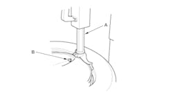
5) Mount the tire according to the tire manufacturer’s instructions being certain to position the machine arm at 6 o’clock with respect to the location of the valve to avoid damage to the sensor (see Figure 2).
6) Inflate the tire to the pressure specified on the Vehicle Certification (VC) label located on the driver door or door pillar. 7) Install the wheel and tire.
8) If a new sensor has been installed it must be activated (see TIRE PRESSURE SENSOR ACTIVATION and trained (see TIRE PRESSURE SENSOR TRAINING). ■
Information for this column comes from the tire pressure monitoring systems data in ProDemand®, Mitchell 1’s auto repair information software for domestic and import vehicles. Headquartered in Poway, Calif., Mitchell 1 has provided quality repair information solutions to the automotive industry since 1918. For more information, visit www. mitchell1.com.
