SUBJECT VEHICLES: Chrysler/Jeep Wrangler – 2011-15
RELEARN PROCEDURE? Yes.
SPECIAL TOOLS NEEDED? Yes, the TPM-RKE analyzer, 9936, with the scan tool.
This tire pressure monitoring system (TPMS) on 2011-2015 Chrysler/Jeep Wranglers consists of sensors attached to each wheel through the valve stem mounting hole, a wireless control module (WCM) and a yellow TPMS telltale lamp.
A TPMS sensor is installed in the spare wheel if the vehicle is equipped with a matching full size spare wheel and tire assembly. The receiver circuit for the TPMS system is integrated into the WCM for non-remote start vehicles. For factory installed remote start vehicles, the remote start antenna is external to the WCM. The WCM can also include the remote keyless entry (RKE) receiver, remote start (if equipped), and the sentry key immobilizer (SKIM) receiver.
All four receivers share a number of common components. The WCM decodes the RF signals transmitted by each of the vehicle’s tire pressure sensors. The decoded information is used to determine if “warning” or “fault” conditions exist within the TPMS.
Warning indicators
If the TPMS detects that the tire pressure in any road tire is going low, beyond the low pressure (lamp) ON threshold, the TPMS will continuously illuminate an indicator lamp. If a system fault is detected, the indicator lamp will flash on/off for 75 seconds and then remain on solid.
Once the low tire pressure warning has been illuminated, the tire pressure must be increased to the recommended cold placard pressure in order for the TPMS warning lamp to be turned off. The system will automatically update and the TPMS warning lamp will extinguish once the updated tire pressures have been received. The vehicle may need to be driven for up to 10 minutes above 15 mph (25 km/h) to receive this information.
Reset procedures
NOTE: If a tire pressure sensor has been replaced, the tire pressure sensors must be retrained.
Once the low tire pressure warning has been illuminated, the tire pressure must be increased to the recommended cold placard pressure in order for the TPMS warning lamp to be turned off. The system will automatically update and the TPMS warning lamp will extinguish once the updated tire pressures have been received. The vehicle may need to be driven for up to 10 minutes above 15 mph (25 kph) to receive this information.
Tire pressure sensor retraining
Using a RF signal, each sensor transmits tire pressure data approximately once every minute. Each sensor’s (transmitter) broadcast is uniquely coded so that the TPMS module can monitor the state of each of the sensors on the four rotating road wheels. The TPMS module automatically learns and stores the sensor’s ID while driving after a sensor has been replaced. Perform one of the following to allow the system to learn the new sensor ID:
- Once the vehicle has remained stationary for more than 20 minutes, drive the vehicle for a minimum of 10 minutes while maintaining a continuous speed above 15 mph (24 km/h). During this time, the system will learn the new sensor ID.
- Use the TPM-RKE Analyzer, 9936, with the scan tool to program the WCM/SKREEM with the tire pressure sensor ID.
NOTE: If a sensor cannot be trained, see appropriate manufacturer service information.
Demount/mounting procedures
CAUTION: The tire should be demounted from the wheel using the tire changer manufacturer’s instructions. Use the following information to avoid damage during the demounting/mounting procedures.
CAUTION: The TPMS has been optimized for the original equipment tires and wheels. TPMS pressures have been established for the tire size equipped on the vehicle. Undesirable system operation or sensor damage may result when using replacement equipment that is not of the same size, type or style. Aftermarket wheels can cause sensor damage. Do not use aftermarket tire sealants or balance beads if the vehicle is equipped with TPMS, as damage to the sensors may result.
NOTE: If a tire pressure sensor has been replaced, the tire pressure sensors must be retrained. See “Reset procedures.”
NOTE: Wheels and tires are match-mounted at the factory. Before demounting a tire from its wheel, a reference mark should be placed on the tire at the valve stem location, to ensure that it is remounted in the original position on the wheel. For match-mounting procedures, refer to the appropriate manufacturer service information.
NOTE: Tire pressure may increase from 2 to 6 psi (14 to 41 kPa) during normal driving conditions. Do not reduce this normal pressure build up.
NOTE: If tires require leak-testing, a water test may be used to check for a leak around the sensor, as long as any water at the valve core is removed when the procedure is completed. Water can be expelled from the core area by pushing in on the core for several seconds, allowing escaping air to drive out any moisture.
Re-inflate the tire as necessary. Install the original valve stem cap.
Tire pressure sensor
CAUTION: Although additional sensors operating at 433 MHz are available and are used in other applications, they are not interchangeable. Always make sure the correct sensor is being used and be sure to replace the sensor with the correct part number.
CAUTION: The cap used on this valve stem contains an O-ring seal to prevent contamination and moisture from entering the valve stem. Retain this valve stem cap for reuse. Do not substitute a regular valve stem cap in its place.
CAUTION: Do not attempt to install a tire pressure sensor in an aftermarket wheel. Use tire pressure sensors in original style factory wheels only. If aftermarket wheels are installed, and therefore do not contain tire pressure sensors, the system will not function properly and the driver will be continuously notified of a system malfunction.
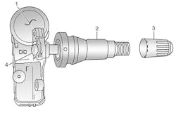
CAUTION: Any time a sensor is to be reinstalled in a wheel, a new valve stem assembly (2) must be installed to ensure air tight sealing (see Figure 1).
Removal
1) Remove the tire and wheel assembly from the vehicle.
2) Demount the tire from the wheel following tire changer manufacturer’s instructions while paying special attention to the following to avoid damaging the pressure sensor. When breaking the tire bead loose from the wheel rim, avoid using the bead breaker in the area of the sensor. That includes both front and rear beads of the tire.
- When preparing to demount the tire from the wheel, carefully insert the mounting/demounting tool 280 degrees +/ -10 degrees from the valve stem, then proceed to demount the tire from the wheel. Use this process on both the upper and lower tire beads.
3) Remove the sensor to valve stem retainer screw (4) and then remove the sensor (1) from the valve stem (2). Remove the valve stem from the wheel (see Figure 1).
NOTE: If replacing the tire pressure sensor, a new valve stem may be pre-mounted to the sensor as an assembly. When reusing the sensor, the new valve stem may come with a mounting screw.
1) Wipe the area clean around the sensor/valve stem mounting hole in the wheel. Make sure the surface of the wheel is not damaged.
2) Insert the new valve stem into the rim and pull through with a standard valve stem installation tool.
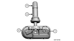
3) If replacing the valve stem only, verify that the flat sides of the brass extension on the bottom of the valve stem are at a 90 degree angle with the wheel (see Figure 2).
4) Position the pressure sensor over the brass extension.
5) Install the retainer screw and torque to 12 in.-lbs. (1.4 N.m).
6) Mount the tire on the wheel following the tire changer manufacturer’s instructions, paying special attention to the following to avoid damaging the tire pressure sensor:
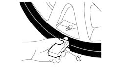
- Rotating wheel tire changers:
Once the wheel is mounted to the changer, position the sensor valve stem approximately 280 degrees from the head of the changer in a clockwise direction before rotating the wheel (also in a clockwise direction) to mount the tire. Use this procedure on both the upper and lower tire beads (see Figure 3).
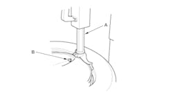
- Rotating tool tire changers:
Position the wheel on the changer so that the sensor valve stem is approximately 210 degrees from the head of the changer in a clockwise direction from the mounting end of the tool (see Figure 4). Make sure the sensor is clear of the lower bead breaker area to avoid damaging the sensor when the breaker rises. Rotate the tool in a counterclockwise direction to mount the tire. Use this procedure on both the upper and lower tire beads.
7) Adjust air pressure to specification. Make sure the original style valve stem cap is securely installed to keep moisture out of the sensor. Install the wheel and tire assembly on the vehicle.
8) Drive vehicle for a minimum of 5 minutes while maintaining a continuous speed above 20 mph (32 km/h). During this time, the system will learn the new sensor ID code and will clear any DTCs automatically. If a sensor cannot be trained, see the appropriate manufacturer’s service information. ■
Torque specifications
Component Ft.-lbs. (N.m)
Lug nut 1/2 x 20 with 60 degree cone 92-132 (125-180)
In.-lbs. (N.m)
Torx screw 11.5 (1.3)
Information for this column comes from Mitchell 1’s “Tire Pressure Monitoring Systems Guide” for domestic and import vehicles. Headquartered in Poway, Calif., Mitchell 1 has provided quality repair information solutions to the automotive industry for more than 80 years. For more information, visit www.mitchell1.com. For archived TPMS articles, visit www.moderntiredealer.com.
To read more TPMS columns, see:


