SUBJECT VEHICLES: 2007-2013 Chrysler/Jeep Compass and Patriot.
RELEARN PROCEDURE? Yes.
SPECIAL TOOLS NEEDED? Yes, an RKE-TPM analyzer used in conjunction with a scan tool.
There are two tire pressure monitoring systems (TPMS) available for the 2007-2013 Chrysler/Jeep Compass and Patriot, a base system and a premium system. The base system does not specify how many tires are low or where they are located. The premium system does so.
The TPMS monitors air pressure in the four road tires. The TPMS uses radio and sensor technology to monitor tire air pressure levels. Sensors, mounted to each road wheel as part of the valve stem, monitor tire pressure, air temperature inside tire, wheel acceleration and the sensor internal battery status for all four active road tires. The sensor will broadcast this information, along with a unique 32-bit ID, to a central receiver circuit located inside the wireless control module (WCM).
In some model years, transponders are mounted in wheel housings (two in the front, and one in the rear) to locate all sensors in each wheel. If a warning or fault condition exists, the WCM will send a bus message request to illuminate the low pressure warning light, to sound a chime, and to display warning messages on the instrument cluster.
The TPMS remains active even if no tire pressure related message is displayed. The sensors lay dormant (Park Mode), then wake and start transmitting (Drive Mode) within 10 minutes when the vehicle travels continuously at speeds over 15 mph (24 km/h). Once the wheels stop rotating for a period of approximately 20 minutes, the sensors shut down until again awakened. While in Park Mode, the sensors still transmit approximately once every 13 hours to let the receiver know air pressure status at that time or when a 1 psi (6.9 kPa) change is detected. If a system fault is detected, the indicator light will flash on/off for 60 seconds, once every 10 minutes.
Tire pressure monitor warning indicators
The TPMS detects that the tire pressure in any road tire is beyond appropriate pressure specification, the TPMS will continuously illuminate an indicator lamp. The TPMS will request a chime once per ignition cycle for each “warning” or “fault” condition detected. A “warning” or “fault” condition will remain enabled until the problem causing the condition is corrected and removed/reset. If equipped, a graphic display of the pressure value(s) with the low tire(s) flashing will appear in the electronic vehicle information center (EVIC). If the warning light is lit continuously due to low pressure in one or more tires, adjust tire inflation to specification. The light will remain on until tire pressure is properly set.
After adjusting air pressure in a tire, allow approximately two minutes for the message or indicator lamp to go out. If the warning light flashes for 75 seconds then remains ON continuously and a chime sounds, there is a problem in the TPMS.
If equipped with the EVIC, in addition to a chime and an indicator lamp flashing, a “Check TPM System” text message will be displayed in the instrument cluster, and the tire pressure graphic display will have “- -” in place of the pressure value. After the flash sequence, the TPMS indicator lamp will remain illuminated. See the appropriate manufacturer service information.
Reset procedures
NOTE: If a tire pressure sensor has been replaced, the TPMS needs to relearn the tire pressure sensor IDs.
If the warning light is lit continuously due to low pressure in one or more tires, adjust tire inflation to specification. The light will remain on until tire pressure is properly set.
After adjusting air pressure in a tire, allow approximately two minutes for the message or indicator lamp to go out.
Tire pressure sensor retraining
The WCM automatically learns and stores the sensor’s ID while driving after a sensor has been replaced. There is no formal retraining procedure necessary. Driving a vehicle with a new sensor, for a minimum of 10 minutes while maintaining a continuous speed above 15 mph (24 km/h), will cause the system to learn the new sensor ID code and will clear any DTCs automatically.
If a sensor cannot be trained, see the appropriate manufacturer service information. A new sensor ID also can be programmed directly into the WCM by using a RKE-TPM analyzer in conjunction with a scan tool. Once the new sensor ID has been programmed, the RKE-TPM analyzer can be used to update the TPMS by activating the sensor.
Demounting/mounting procedures
CAUTION: The tire should be demounted from the wheel using the tire changer manufacturer’s instructions. Use the following information to avoid damage during the demounting/mounting procedures.
CAUTION: The TPMS has been optimized for the original equipment tires and wheels. TPMS pressures have been established for the tire size equipped on the vehicle. Undesirable operation or sensor damage may result when using replacement equipment that is not of the same size, type and/or style. Aftermarket wheels can cause sensor damage.
NOTE: If a tire pressure sensor has been replaced, the tire pressure sensors must be retrained. See reset procedures.
NOTE: Wheels and tires are match-mounted at the factory. Before demounting a tire from its wheel, a reference mark should be placed on the tire at the valve stem location, to ensure that it is remounted in the original position on the wheel. For match-mounting procedures, refer to appropriate manufacturer service information.
Tire pressure sensor
IMPORTANT: This vehicle uses the 315 MHz TPMS. Although 315 MHz and 433 MHz sensors are identical in size and shape, they are not interchangeable. Always make sure the correct sensor is being used. On a domestic vehicle, the TPMS sensor operates on a 315 MHz radio frequency. Imported vehicle sensors operate on a 433 MHz radio frequency. The 315 MHz sensors can be easily identified by a white outline oval (black center) insignia on the sensor body.
The 433 MHz sensors can be easily identified by either a solid white oval insignia on the body or a solid white oval insignia with 433 printed in the center. The sensors are identical except for the oval insignia. The 433 MHz sensors can either have a black or grey sensor body.
CAUTION: The use of tire sealants is strictly prohibited for vehicles equipped with TPMS. Tire sealants can clog tire pressure sensors.
CAUTION: Before installing a tire pressure sensor, ensure you have the correct sensor. As noted, sensors can be easily identified by a black sensor body with a white outline (not solid) oval insignia on the sensor body. Copy the ID number off of the new pressure sensor before installing it into spare tire.
CAUTION: To prevent moisture and contamination from entering the valve stem, the cap used on this valve stem contains an “O” ring seal. Retain the original valve stem cap for reuse. A regular valve stem cap cannot be used as a substitute. After inspecting or adjusting the tire pressure, always reinstall the valve stem cap. This will prevent moisture and dirt entry into the valve stem, which could damage the wheel rim sensor.
CAUTION: The valve stem used on this vehicle is made from aluminum, and the core is nickel-plated brass. Retain the original valve stem core for reinstallation. Do not substitute a valve stem made of a different material, as the different metals will cause corrosion.
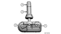
CAUTION: Any time a sensor is to be installed in a wheel, a new seal and washer must be installed on the stem to ensure airtight sealing. The nut and valve core should also be replaced (see Figure1).
CAUTION: DO NOT reuse the sensor-to-wheel grommet. Always use a new grommet when installing a pressure sensor and properly torque the sensor nut.
Removal
1) Raise and support the vehicle. Remove the tire and wheel assembly from the vehicle.
2) Let the air out of the tire.
3) Remove the sensor nut.
NOTE: Before reinstalling an existing tire pressure sensor, replace the valve core, seal and metal washer at base of valve stem to ensure proper sealing (see Figure 1).
1) Wipe the area clean around the sensor/valve stem mounting hole in the wheel. NOTE: Make sure the surface of the wheel is not damaged.
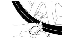
CAUTION: To avoid damaging the sensor antenna strap, hold pressure against the rear of the metal valve stem while the sensor is inserted through the wheel mounting hole and the nut is installed (see Figures 2 and 3).
2) Insert the sensor through the wheel as shown keeping pressure against the rear of the metal valve stem. The potted side of the sensor is to be positioned toward the wheel. Do not attempt to mount the sensor otherwise, or damage may occur.
Install the sensor nut (with pressed-in washer) by hand (see Figures 3 and 4).
NOTE: Before tightening the sensor nut, push downward on the sensor housing in an attempt to make it flush with the interior contour of the wheel.
3) Using a thin-walled socket, install the sensor nut. While holding the sensor in position, tighten the sensor nut to 71 in.-lbs. (8 N.m).
CAUTION: Over-torquing the sensor nut by as little as 106 in.-lbs. (12 N.m) may result in sensor separation from the valve stem. Under this condition, the sensor may still function; however, the condition should be corrected immediately.
4) Mount the tire on the wheel following the tire changer manufacturer’s instructions, paying special attention to the following to avoid damaging the tire pressure sensor.
Rotating wheeltire changers
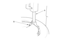
Once the wheel is mounted to the changer, position the sensor valve stem approximately 280 degrees from the head of the changer in a clockwise direction before rotating the wheel (also in a clockwise direction) to mount the tire. Use this procedure on both the upper and lower tire beads (see Figure 5).
Rotating tool tire changers
Position the wheel on the changer so that the sensor valve stem is approximately 210 degrees from the head of the changer in a clockwise direction from the mounting end of the tool (see Figure 6).
Make sure the sensor is clear of the lower bead breaker area to avoid damaging the sensor when the breaker rises. Rotate the tool in a counterclockwise direction to mount the tire. Use this procedure on both the upper and lower tire beads.
5) Adjust air pressure to specification. Make sure the original style valve stem cap is securely installed to keep moisture out of the sensor. Install the wheel and tire assembly on the vehicle.
6) The new tire pressure sensor will need to be retrained. See reset procedures.
Torque specifications
Component Ft.-lbs. (N.m)
Wheel nut (1) 100 (135)
In.-lbs. (N.m)
Tire pressure sensor nut (2) 66 (7.5)
1) Do not use chrome-plated lug nuts with chrome-plated wheels.
2) Over-torquing the sensor nut by as little as 106 in.-lbs. (12 N.m) may result in sensor separation from the valve stem. As the article notes, under this condition, the sensor may still function; however, the condition should be corrected immediately.
Information for this column comes from Mitchell 1’s “Tire Pressure Monitoring Systems Guide” for domestic and import vehicles. Headquartered in Poway, Calif., Mitchell 1 has provided quality repair information solutions to the automotive industry for more than 80 years. For more information, visit www.mitchell1.com.
For archived TPMS articles, visit www.moderntiredealer.com.
To see more TPMS articles, click:
TPMS: General Motors/Chevrolet Colorado and Canyon, 2006-12
2011-2015 Chrysler Ram Pickups


